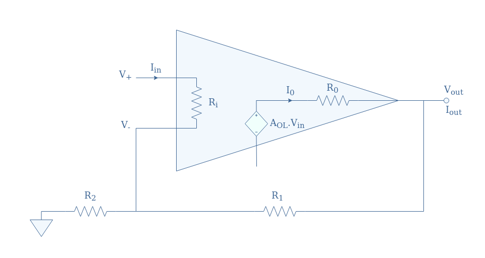
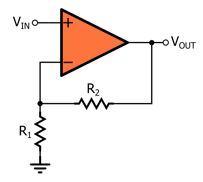
Closed-Loop Gain Calculation. The symbol used to designate an operational amplifier is shown in Figure 1.1. The amplifier shown has a differential input and a single output. The input terminals marked – and + are called the inverting and the non-inverting input terminals respectively.. Op Amp Non-inverting Amplifier Gain Equation. Let’s derive the non-inverting amplifier gain equation using the schematic of Figure 3, which has distinct resistors, R 1 and R 2, in the negative feedback path. Figure 3. SPICE circuit schematic with node numbers for simulation of the op amp non-inverting amplifier . Beginning from the op amp open.

Op amp comparator circuits Inverting and non inverting Electronzap
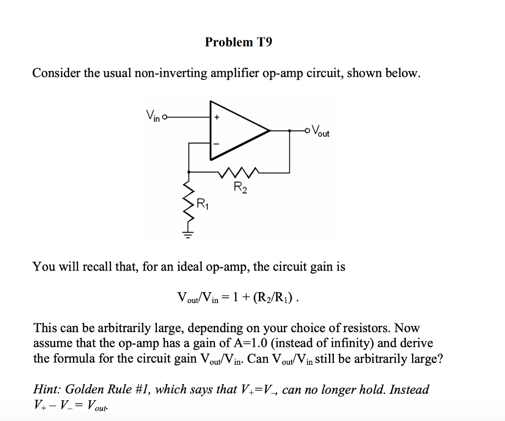
Solved Problem T9 Consider the usual noninverting amplifier
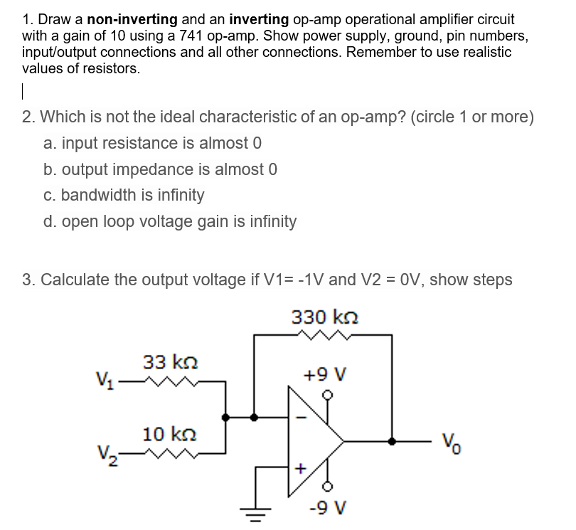
Solved 1. Draw a noninverting and an inverting opamp

Calculating Voltage Gain & Input Current of a Noninverting Operational Amplifier Circuit
Noninverting OPAMP
Basic Amplifier Configurations the NonInverting Amplifier Video Tutorial

Op Amp Open Loop Inverting, Non inverting and Differential Mode YouTube
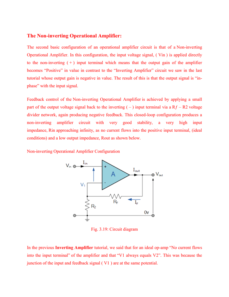
The Noninverting Operational Amplifier
notes Non Inverting Op Amp Configuration OER
Non Inverting Amplifier(OPAMPs) » OPAMP tutorial

NonInverting Amplifier HyperElectronic
Noninverting OpAmps (Example 2)
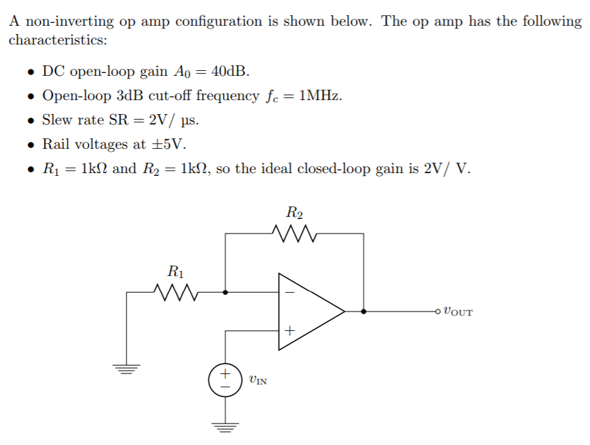
Solved A noninverting op amp configuration is shown below.
Can you draw the block diagram for a noninverting operational amplifier and derive the gain

Electronic Non inverting opamp gain LTspice Valuable Tech Notes
Non Inverting Op Amp Schematic

Non Inverting Amplifier(OPAMPs) » OPAMP tutorial
NonInverting Op Amp Electronics Reference
Online Tutorial On Calculating NonInverting Operational Amplifier Gain And Output Voltage YouTube
Circuit analysis of op amp noninverting integrator SolveForum S2
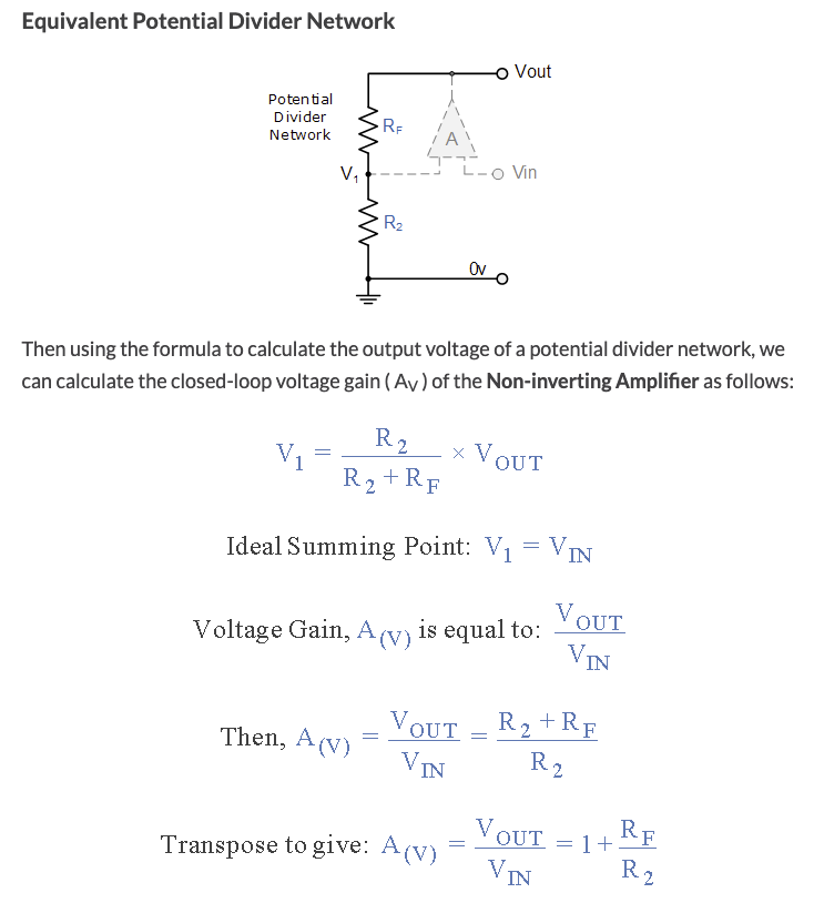
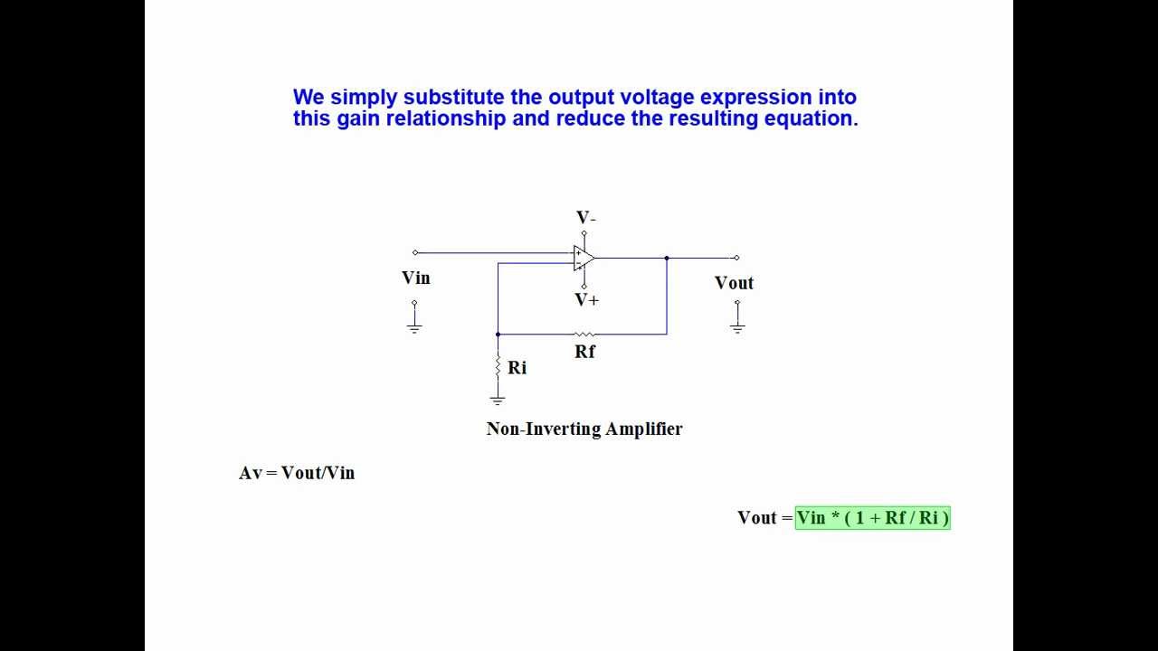
An operational amplifier (op-amp) is a high-gain voltage amplifier with two inputs, inverting (-) and non-inverting (+), and a single output. Choosing between inverting and non-inverting op-amp configurations depends on the application’s requirements, taking into consideration phase requirements, gain, input and output impedance, common-mode rejection, and other factors.. Non-inverting Operational Amplifier Voltage Follower. In this non-inverting circuit configuration, the input impedance Rin has increased to infinity and the feedback impedance Rƒ reduced to zero. The output is connected directly back to the negative inverting input so the feedback is 100% and Vin is exactly equal to Vout giving it a fixed gain.
